Zener Barrier Wiring Diagram
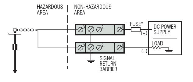
The voltage is limited/clamped by a zener diode and the current limited by an output resistor. The fuse is there to protect the zener diode.
Intrinsically Safe Design Proheat, Inc. (502) 2221402
The breakdown voltage of the diodes is not exceeded in normal operation.

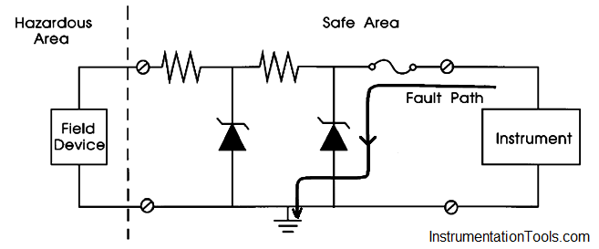
Zener barrier wiring diagram. Safety barriers featuring an ext remely broad application area. The breakdown voltage of the diodes is not exceeded in normal operation. The key to safety is the intrinsically safe earth.
(max 200m / vprnp guage pressure · w(waterproof connector): The earthing or grounding of zener barrier installations in intrinsically safe instrumentation and control systems is a common source of concern to installation engineers. The barriers limit the el ectrical energy towards the ha zardous area by means of a combination of zener diodes, resistors and fuses.
The operating range of a zener barrier must therefore be such that it is below the zener voltage, so that the leakage current is restricted to a minimum. Typically the tip of a boom gate rises in a vertical arc to a near vertical position. Circuit of the connecting wiring in the hazardous area or a connection to earth of the wiring attached to terminal 1, as the fuse blows.
Seven 'key' mtl700 range of models are highlighted in the sales literature as meeting most process control requirements. These models and their applications are listed in table 1. A wiring diagram is a streamlined conventional photographic depiction of an electrical circuit.
The mtl700p barriers are mechanically identical to the mtl700 range of barriers and are therefore compatible with all mtl700range accessories. Leading distributor of electronic components, electric. Rl ac input source** zener barrier ** input power from source not greater than 250 vac stud cover must be in place when barrier is in use.
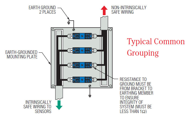
Dummy barrier, mtl7799 weight 140g approx mounting and earthing by 35mm top hat din rail dimensions (mm) mtl7700 range key barriers summarised how they work all mtl7700 range barriers are based on the same simple principle. Zener barriers the applied voltage is increased. The underlying concern breeds the suspicion that satisfactory earthing is difficult.
The fuse will open when the zener diode conducts thereby further protecting the circuit. To ensure the safety of such a wiring, point t1 must be connected to ground as illustrated in fig. It is designed to limit the amount of energy that could appear in an electrical circuit passes through the hazardous area despite the connection before the barrier.
Our zener barriers include positive. The zener diodes in the zener barrier are connected in the reverse direction. A resistor, at least two zener diodes, and a fuse.the resistor limits the current to a specific value known as the short circuit current, isc.the zener diode limits the voltage to a value referred to as.
Zener barriers are normally tested to check that at the prescribed voltage the leakage current is smaller than 10 µα. The zener barrier prevents the transfer of unacceptably high energy from the safe area into the hazardous area. Circuit diagram for an intrinsically safe barrier is shown in figure 2.
A zener barrier is an associated equipment that is installed in the safe area. Switches 8 7 6 5 4 3 2 1 term. Z 722 (for digital current output) b) wiring with zener barrier pepperl + fuchs mod.
Wiring diagram 12.0724.0001 page 1 of 2 _____ 02/28/2002 a) wiring with zener barrier pepperl + fuchs mod. Zener barrier wiring diagram d.c. Zener barrier wiring diagram d.c.
When considering the intrinsically safe circuit in a control system, there are three main components: A zener barrier is a simple device where the voltage & current (power, energy) is limited into the hazardous area. If this voltage is exceeded, due to a fault in the safe area, the.
Our bulletin 937z zener barriers provide protection for electrical signals within hazardous areas. Typical intrinsic safety barrier wiring diagrams i. They also prevent the transfer of unacceptably high energy from the safe area into the hazardous area.
Z 788.h (for analog current output) hazardous area safe area power supply negative important: These barriers feature a narrow profile of just 12.5 mm to maximize control panel space. 1) the field device (can be either a simple or.
The zener diodes in the zener barrier are connected in the reverse direction. If this voltage is exceeded, due to a fault in the safe area, the. The zener barrier prevents the transfer of unacceptably high energy from the safe area into the hazardous area.
The zener barriers mount on 35 mm din mounting rail. There are three components to a barrier that limit current and voltage: To set up a boom barrier you must first install a loop.
Without it, there is no protection. Zener barrier wiring diagram d c.
Zener Barrier Z961/Z964 /MinebeaMitsumi Inc. Sensing Device BU

Zener Diode Barrier Principle Instrumentation Tools

The Safety barriers Instrumentation and Control Engineering
SAFEPAK® Relays and Zener Barriers Installation and Maintenance

Gems Sensors 111952 Single Channel Zener Barrier, 303 ohms Resistance, +20 VDC Voltage, 125 mA

How Zener Barriers work
How Zener Barriers work


How Zener Barriers work

How To Calculate Zener Series Resistor

Fire and Gas System Intrinsic Safety (IS)
Zener Barrier with Negative Ground Gems Sensors
Zener barrier MTL7787+ SPECTRA BALTIC Widest Range of Electronics Systems Components

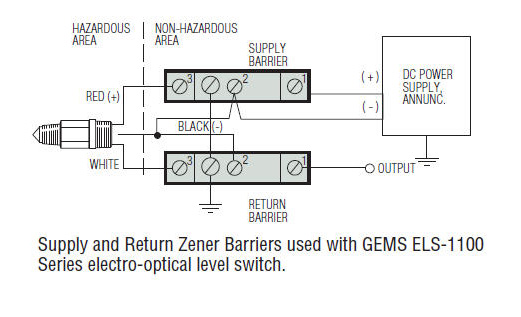
65800 Zener Barrier Applications Gems Sensors

Extech Hazardous area specialist products supplier

Intrinsic Safety and Safety Barriers Learning Instrumentation And Control Engineering
How Zener Barriers work

Intrinsic Safety Explosionproof Barrier Zenerbarrier(for Transducer) series CO.,LTD
MilWorks PRODUCT


Intrinsic Safety and Safety Barriers Learning Instrumentation And Control Engineering